Drone Setup
This readme contains the setup of a drone to be used with ardupilot and ultimately allow for autonomous flight to a target.
Firmware version is pinned: ArduCopter 4.6.3
Everything below was written for and verified against ArduCopter 4.6.3. Parameter
names move between releases (e.g. RNGFND1_MIN_CM/RNGFND1_MAX_CM in 4.6 became
RNGFND1_MIN/RNGFND1_MAX in 4.7, RTL_ALT became RTL_ALT_M), and ArduPilot
silently ignores parameter names it does not know. A setup that "loaded fine"
can leave a sensor unusable with no error shown. Do not install "latest"; install
4.6.3 and check the version banner in Mission Planner before changing anything.
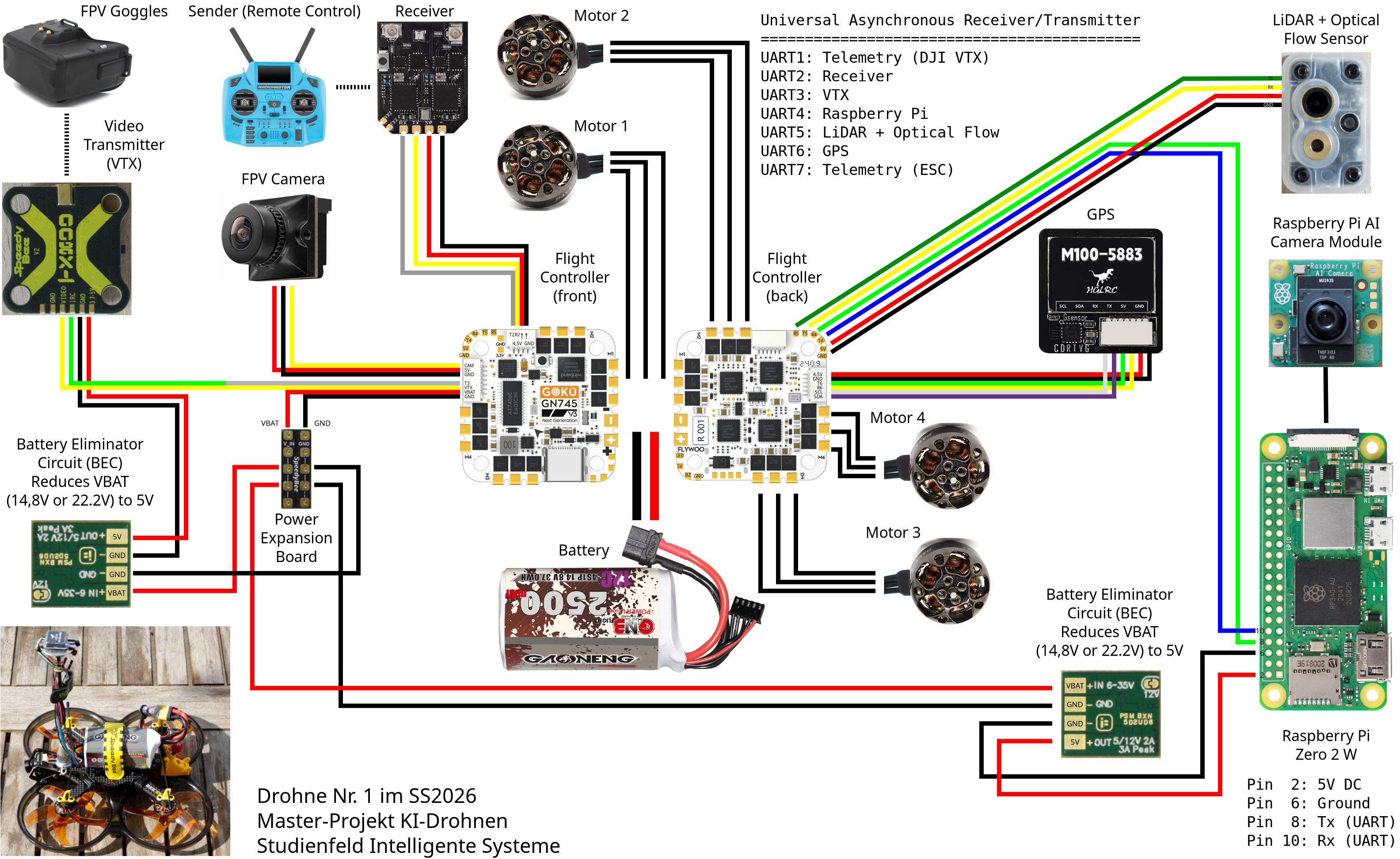
The drone we used has the following components:
- Frame: SpeedyBee BEE35 Pro 3.5 CineWhoop Frame Kit
- Flightcontroller: Flywoo GOKU GN745 (STM32F745, 216MHz, 1MB Flash) 45A AIO 2-6S AM32
- Receiver: Radiomaster XR4 Gemini Xrossband Dual-Band ELRS receiveer, Firmware ExpressLRS 4.0.0
- Camera: RunCam Phoenix 2 1000TVL 155FOV Analog
- Video sender: SpeedyBee TX800 VTX
- VTX-Antenna: TrueRC Singularity 5.8GHz RHCP SMA
- Motors: Emax Eco II 2004 3-6S 3000KV
- Propellers: Gemfan 90mm D90-5 3.5" Ducted 5-rotor Propeller
- GPS: HGLRC M100 with integrated compass
- additional Hardware
- MicroAir MTF-01P
- Raspberry Pi Zero 2 WH The wiring can be seen here:
Installaltion of Ardupilot
Download correct firmware
For our installation, we first need our firmware to flash the flight controller, in this case we are using the Flywoo Goku GN745 flight controller, that is using a STM32F745 controller. For the default version, we can download our firmware from https://firmware.ardupilot.org/, where we can find firmware for a multitude of different drone types. We are using the copter firmware pinned to the stable release 4.6.3 (see the warning at the top, do not take "latest"): https://firmware.ardupilot.org/Copter/stable-4.6.3/FlywooF745/, where we want to download the file ending with bl.hex (it includes the bootloader).
This approach works generally to be able to just fly a drone, but as our goal is to create an autopilot using a lidar and optical flow combination, as well as an onboard computer, we need a custom version of ardupilot, which we can create under https://custom.ardupilot.org/. On the upper right we can see the option to create a new build:

This leads to a page where we can choose our drone type, the version we want to use (choose the 4.6.3 stable tag, matching the pinned project version, not "latest") and the flight controller we are using

and below are all options listed, that ardupilot can have. Most basic options shoud already be in the default version, but especially if extra sensors and functionality that goes above manually piloting the drone are needed, we will need to change our settings. For our personal use case we will add a mavlink optical flow sensor, enable OpticalFlow fusion for EKF3
and to use our onboard computer we will also need the Enable Mode Guided NoGPS option:
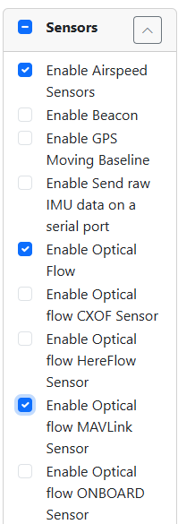
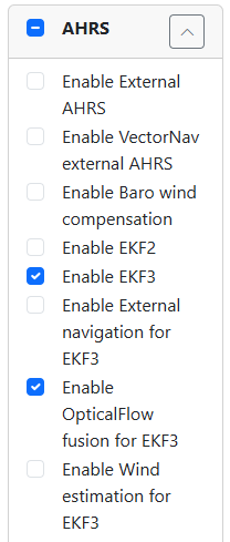
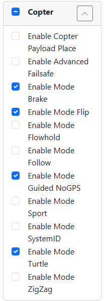
After we made our selection of needed options, we can generate our build using the button on the lower right

The build will then be shown on https://custom.ardupilot.org/, where, after the build finished, we can download it

And we are once again interested in the file ending with bl.hex, as this file contains the bootloader.
Install firmware using STM32 Cube Programmer
We can download the STM32 cube programmer through the website of STMicroelectronics https://www.st.com/en/development-tools/stm32cubeprog.html.
To install the Firmware onto our drone, we first have to start the Device Firmware Update(DFU) mode of the drone, which can be achieved by pressing the Boot button, or by manually bridging the boot pads, depending on the flight controller and connecting the drone to our computer through a USB cable while keeping the button pressed. For the flight controller we are using we see the boot button as seen here:
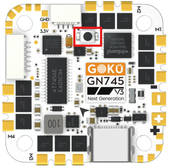
In case there is already a firmware installed, there is often an option to use software to set the flight controller into DFU mode.
Once we have set the drone into DFU mode, we can use the STM32 cube programmer to erase and reprogram our flight controller. On the upper right we need to use the correct settings to connect to our drone. As we are connecting our drone using USB, we choose the corresponding setting and set the used port. Pressing connect then connects our drone to the program
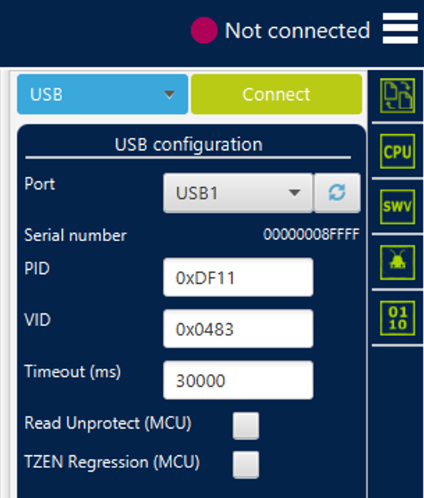
After we succesfully connected, we can use the option tab on the upper left to navigate to the erase and programming page.
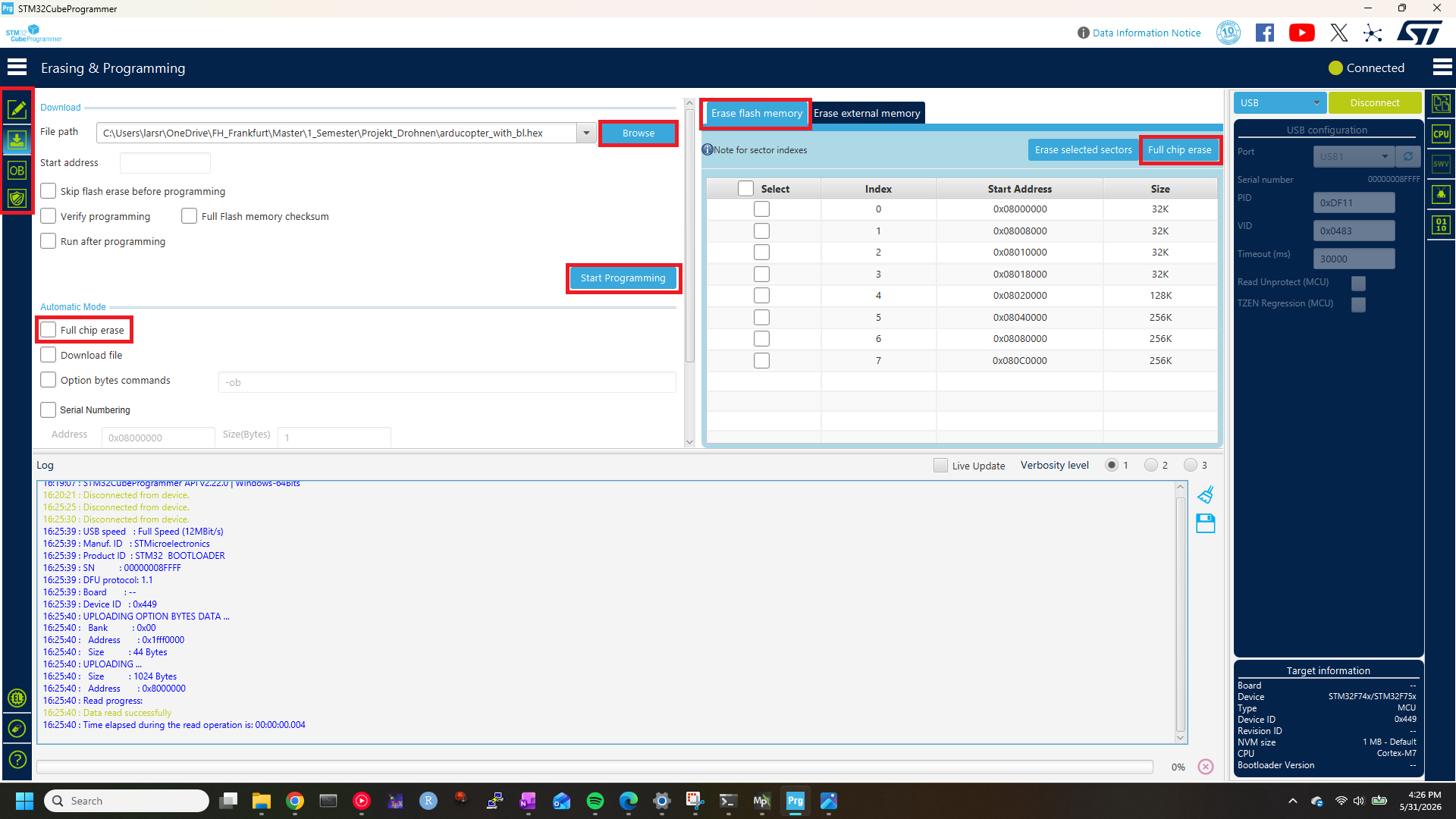
First we have to erase our chip. We can manually erase the chip using the middle window called Erase flash memory, and choose the Full chip erase function. We can also check the Full chip erase option under automatic mode, that will erase the chip before programming.
After the chip is erased, we can choose the bl.hex file we downloaded in the earlier section using the browse tab in the leftmost window and press programming. This will install the firmware onto our drone, and after the programming is done, we can disconnect and restart the flight controller, which completes the installation.
Initial drone setup
To setup our drone we are using the Mission planner available under https://ardupilot.org/planner/docs/mission-planner-installation.html. After downloading and starting the apllication, we connect our drone using USB (the drone does not have to be in DFU mode) and click the connect button on the upper right of the mission planner.

If the drone is already connected through USB, the mission planner will generally set the right port automatically, if this is not the case, we might need to manually choose the correct port using the drop down menu.
Our first steps will be to set the mandatory hardware parameters, that can be found under the setup menu in the upper left:
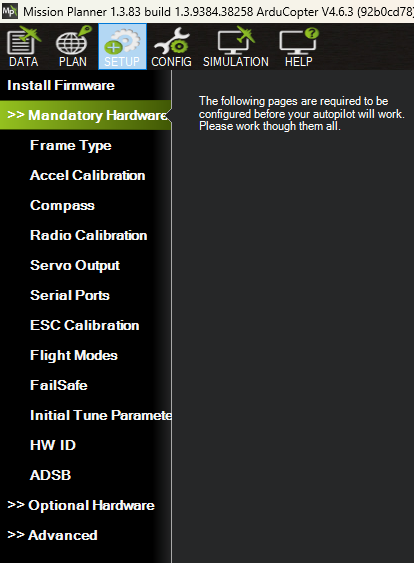
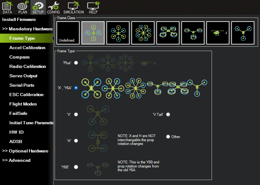
Frame Type
First we look at the Frame Type. Ardupilot supports a lot of different frame types, from different copters to planes and even land and water vehicles, but as we have the copter firmware installed, we will only get approptiate options. In our case we have a quadcopter, that we can choose first though the upper image and then specify using the corresponding options. In our case, the frame is in X form.
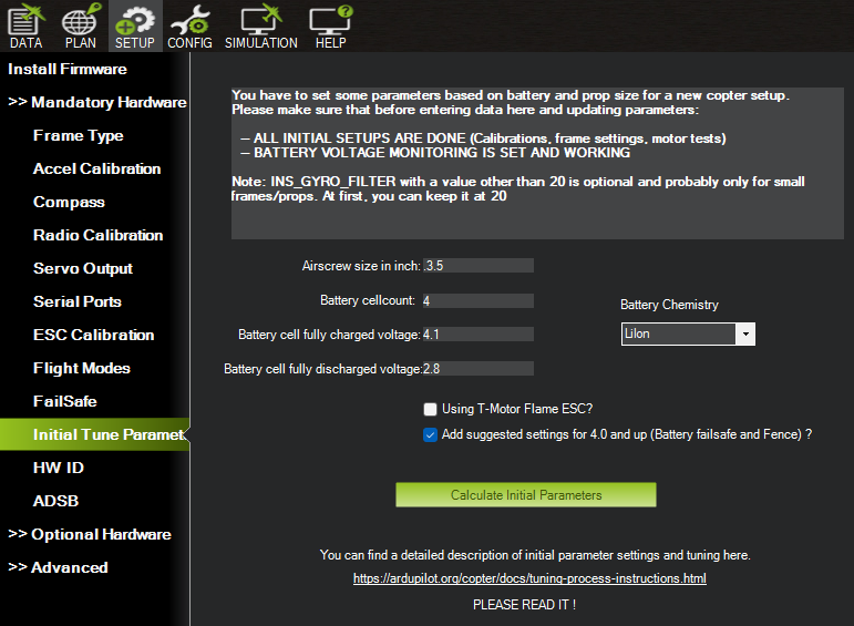
Initial tuning parameters and linear thrust
The next mandatory configuration we will look at are the initial tuning parameters. They comprise of information about the propellers we are using, in our case the size is 3.5 inch, and information about the used batteries. We are using 4 LiIon cells, with fully charged voltage set at 4.1 and fully discharged voltage set to 2.8. Further, as we are using a current version of Ardupilot, we can check the 'Add suggested settings for 4.0 and up' checkbox. These settings are used by the mission planner to calculate initial settings for our PID(Proportional Integral Derivative) controllers, and sets some security functions like battery failsafes, that will trigger warnings and return to launch on low cell voltage, or geofence limits for altitude and distance to prevent flyaways.
The goal of the our initial settings is to have a thrust curve of the motors that is as linearly as possible. There are three main reasons that cause non-linear thrust:
- Voltage sags as throttle increases.
- Incorrectly set endpoints in PWM range
- Non.linearity in thrust produced by Propeller, ESC and Motor
The initial tuning parameters, as already discussed, set the initial parameters for the battery and PID parameters. We will look at the most important options that will be set and might have to be manually changed for better performance.
Voltage Settings
For setting the voltage, we have these main parameters:
- MOT_BAT_VOLT_MAX: Sets the maximum voltage of the battery(4.1V in our case)
- MOT_BAT_VOLT_MIN: Sets the minimum voltage of the battery (2.8V)
- MOT_OPTIONS:
- 0 for default set compensated voltage.
- 1 to use raw voltage, this might improve the tuning results for light drones.
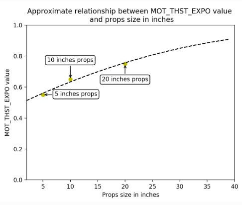
- MOT_THST_EXPO: This controls the motor thrust curve exponent, that is used to correct the non-linear relationship betweem the controllers throttle stick and the actual thrust that is produced by the motors. A linear relationship would mean we get the exact thrust that is indicated by the thrust stick position. 10% increase in thrust stick position would mean 10% increase in throttle. This would be the relation when ´MOT_THST_EXPO` is set to 0. Sadly this is not the case in most situations and the thrust increases exponentially relative to the motor RPM, because of aerodynamics. For professional use, we would have to use a thrust stand to measure the true thrust given our combination of motor, ESC and propeller. But for general use , it is often suffcient to use the following graph:
PID controller initial setup
We will first introduce the PID controller that is used by ardupilot. PID stands for Proportional, Integral and Derivative.
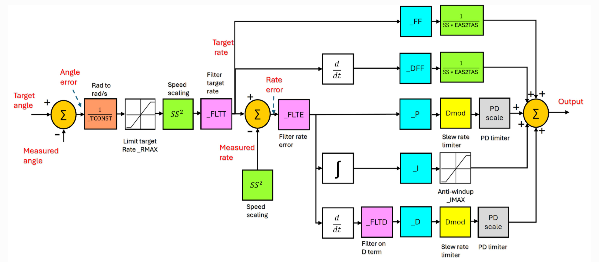
As we can see in the image of the PID-Controller flow diagram, we have two more terms associated with the ardupilot PID-controller. These are the Feedforward(FF) and derivative Feedforward (dFF) terms. The basic idea is the following. When we are controlling the drone and want to move along one of the pitch or roll axes, we will have the actual angle of the drone that is measured in the moment, and we will have a target angle, where we would like our drone to be. The difference between those two angles is called the angle error.
In our image we see multiple blocks that influence our angle error:
- Rad to rad/s \(\dfrac{1}{\\_ TCONST}\): Here the angle error is converted into an angular rate that is based on the time constant
_TCONST. - Limit target rate _RMAX: Ardupilot allows us to set maximum angles the controller will not exceed. This term limits the possible angle to that maximum.
- Speed scaling: Aerodynamic properties change based on the speed of the vehicle, thus the control gains have to be scaled on the current airspeed to maintain stability. We see in our image that multiple green blocks are dependent on the current spped of the drone.
- Filter target rate: A low-pass filter that smoothes the demanded target rate.
After we have the target rate with which to change our angle, we basically see two components. The first leads to the feed forward paths. They anticipate the control effort needed based on the target rate to improve the response time, meaning they directly act based on the target rate. The important point is, that they do not depend on the error and acts before it can build up, reducing delay between target and actual values.
- Feed-forward path
_FF: Here the target rate is multiplied by the feed-forward gain_FFand it is divided by \(SS\cdot EAS2TAS\). \(SS\) is once again the speed scaling parameter. \(EAS2TAS\) is a conversion rate that converts the equivalent airspeed(EAS), a measure of the actual impact of the airpressure on the drone, to the true airspeed(TAS), which is the physical speed of the aircraft relative to the airmass it flies through. - Derivative feed-forward path: Here we take the derivative of the target rate, where we get the angular acceleration. If we move the joystick rapidly, then the derivative feed-forward path will immediatly accelerate faster.
The other component is based on the feedback paths that try to eliminate the rate error. To get the rate error, we calculate the difference between the smoothed target rate and the measured rate that has been scaled through a speed scaling block. After the calculation, the rate error is, similar to the target rate, filtered by a low-pass filter, to remove high frequency sensor noise. This error is then forwarded to our PID-components, that give the PID-controllers their name:
- Proportional component (P): The proportional component directly responds to the current error value and produces output that is proportional to the magnitude of the error. In the image we see that the error is multiplied by a proportional gain, that then is passed through a slew rate limiter and the PD limiter. The slew rate is the speed of change of the proportional and derivative components, which is limited by the Dmod block, that ensures the computer does not request movements faster than the physical hardware is capable of moving. The PD limiter places a ceiling and floor on the combined Proportional and Derivative demands and ensures that the feedback loop cannot demand extreme movements.
- Derivative component(D): The derivative component predicts the future error by assessing the rate of change of the error and dampens the movements as to not overshoot the target angle. It looks at how fast the error is changing and if it moves toward the target rate too quickly, the
_Dblock will slow down the momentum preventing the drone from overshooting and oscillating. Both the Dmod block and PD limiter still have the same function already explained earlier. - Integral component (I): The integral component considers the cumulative sum of past errors to address residual steady state errors that persist over time. It basically adds up the error over time and pushes harder the longer the error persists. An example would be a constant wind that pushes the drone off course. The Integral component builds up pressure to counteract it. The anti-windup block limits the itegral to increase indefinetly, for example when an actuator hits its physical limits the integral component would theoretically keep building up, if there is no limit given.
The actual output for the motors is then given as a sum off each component [ FF + DFF + P + I + D ]
On the ardupilot copter, we have generally 3 rate controllers, one for roll, pitch and yaw and each of the blocks we see in the image can be tuned. Here we will only look at the initial tuning parameters we will set before the first flight, they are intended to get the PID controller acceleration and filter settings into the right approcimate range for our drone.
- INS_ACCEL_FILTER: This parameter defines the cutoff frequency for accelerometers and can be set to lower values in case there are very high vibration levels in the aircraft. The default values is 10hz.
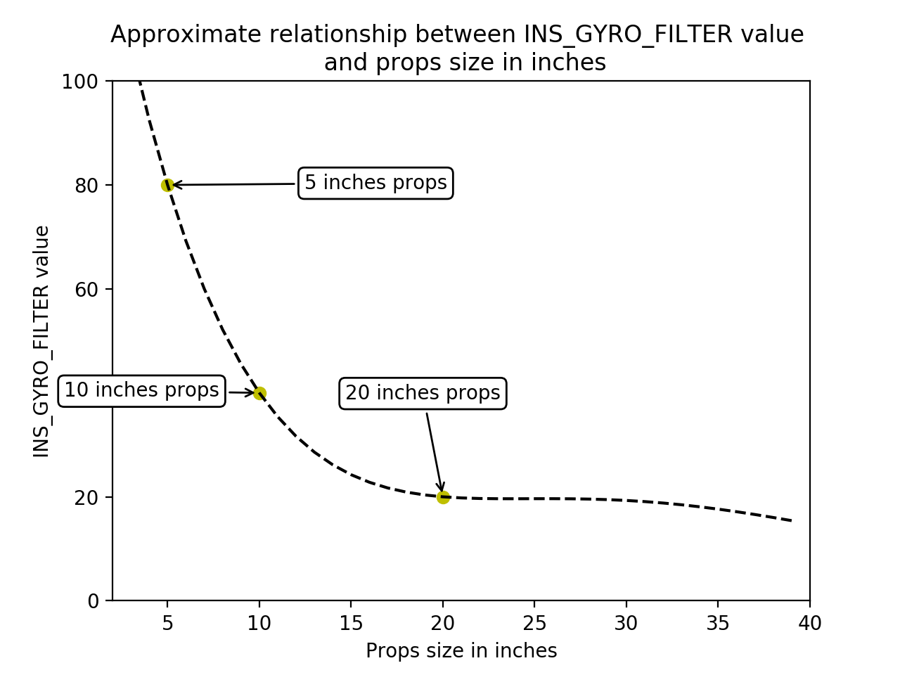
- INS_GYRO_FILTER: This parameter defines the cutoff frequency for gyroscopes. Once again, if there are very high vibration levels in the aircraft, it can be set to a lower value. The default value depends on the size of the propellers and can be approximated using the following graph:
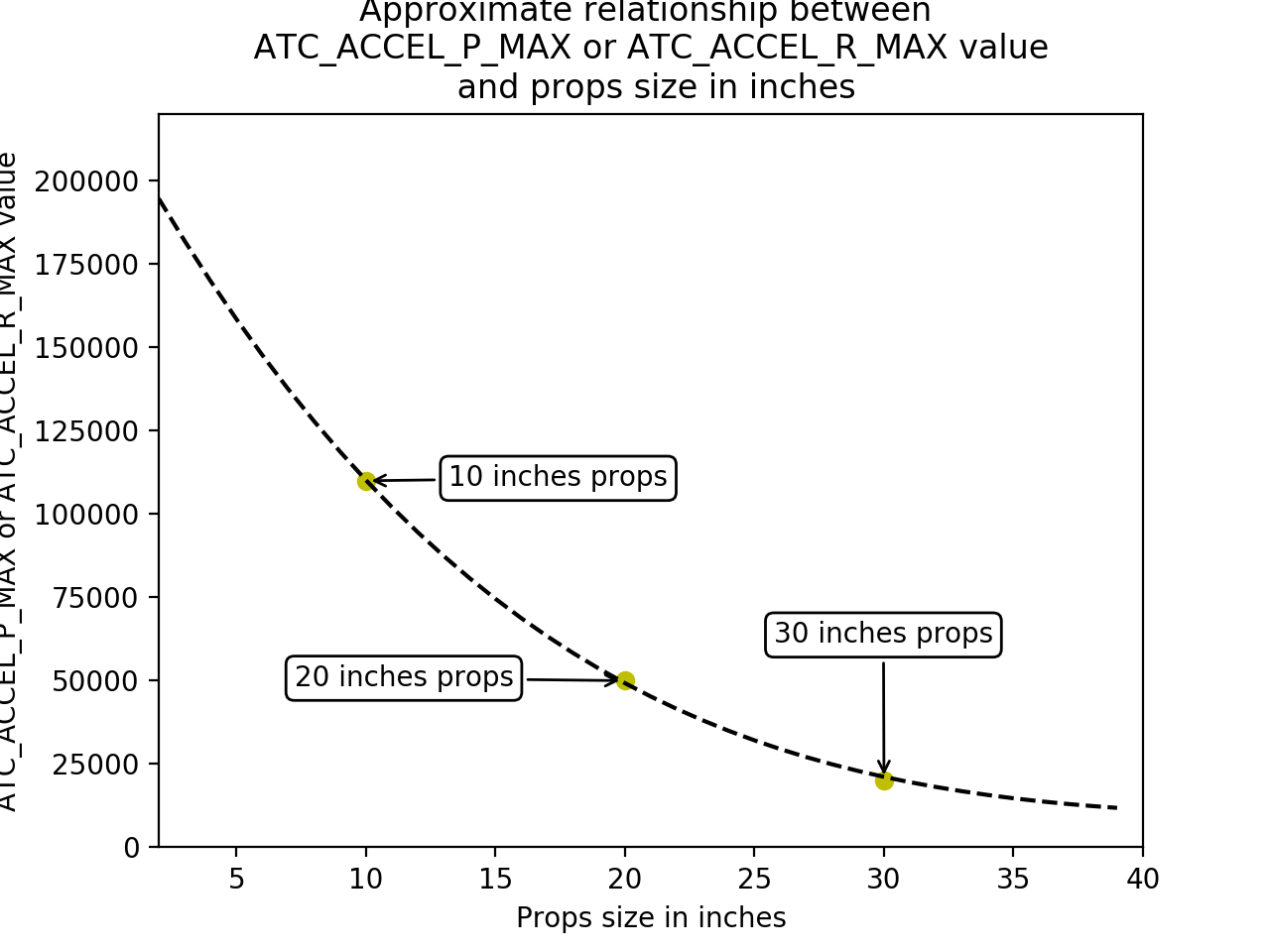
- ATC_ACC_P_MAX and ATC_ACC_R_MAX: Both those parameters set the maximum acceleration for pitch and roll and the unit is degrees per square second. It is once again dependend on the propeller size and will be automatically set using the initial tuning parameters. once again a graph is used to approximate the max values:
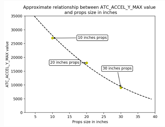
- ATC_ACC_Y_MAX: This parameter sets the maximum acceleration for the yaw axis. It is also dependend on the propeller size and approximated by the initial tuning parameters. The graph that shows propeller size in inches to the maximum yaw acceleration is given here:
The Following parameters should look familiar, as they define the low-pass filters used in our PID controller for each axis. They are by default all set to half the gyro filter frequence. Only the filter for the yaw rate error differs.
- ATC_RAT_PIT_FLTD: INS_GYRO_FILTER / 2
- ATC_RAT_PIT_FLTT: INS_GYRO_FILTER / 2
- ATC_RAT_RLL_FLTD: INS_GYRO_FILTER / 2
- ATC_RAT_RLL_FLTT: INS_GYRO_FILTER / 2
- ATC_RAT_YAW_FLTE: 2
- ATC_RAT_YAW_FLTT: INS_GYRO_FILTER / 2
Accel Calibration and Orientation
Before we can calibrate the acceleration, we first need to make sure the board alignment is how it is supposed to be. We can change the alignment going to the Config tab, then to the Full Parameter List, where we want to look for the AHRS_ORIENTATION parameter.
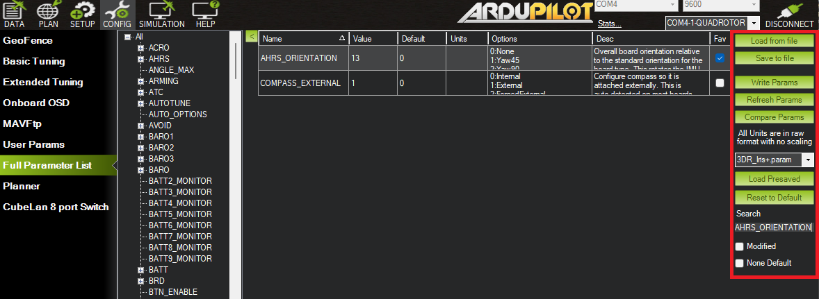
On the right of the image we see some of the most important options used in the Full Parameter List. FIrst we see the options to load from and save to file. The later option saves the full parameter list to a text file, which can then be loaded through the load from file option. It is highly recommended to save the parameters before major changes, so it is easily possible to revert to an earlier parameter selection.
The writing params option is used to finalize the changes made in a session and write them onto the Parameter List. To make changes persistent, they will have to be written into the files. Another important function is the Compare Params option. This allows us to compare our current parameters to different parameter text files, we might have saved to file earlier, allowing us to easily look at changes between different parameter lists.
On the bottom on the right we can also see the search bar, that allows us to look for certain strings in the name of the parameters. As there are lots of parameters, the search function is incredibly useful. Here we are searching for the AHRS_ORIENTATION parameter. This parameter allows us to change the orientation of the flight controller. we can give different values for yaw, roll and pitch values, that rotate a given degree around the axes seen in the following image:
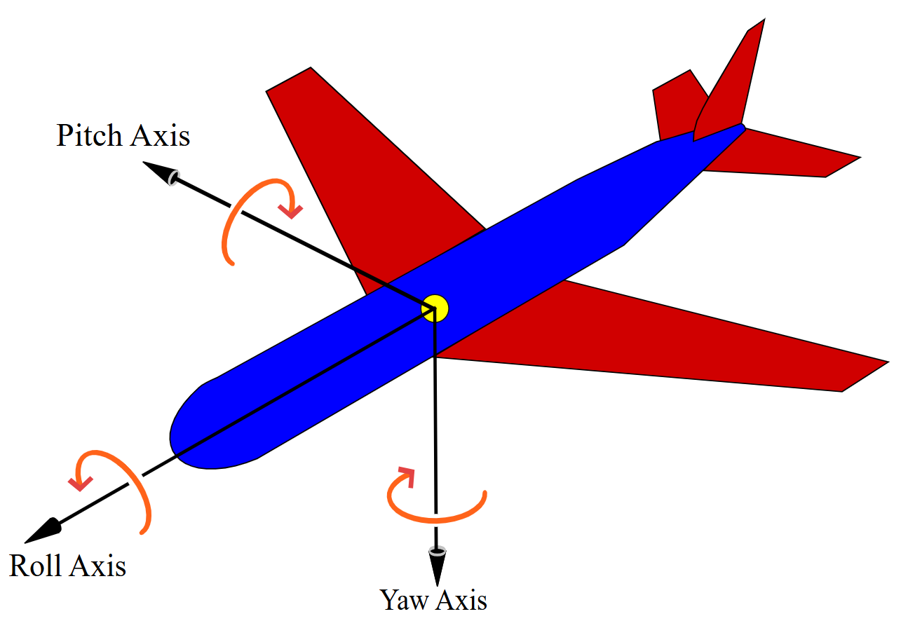
We can see that our drone has the AHRS_ORIENTATION value 13, that gives us a 225 degree yaw rotation and a 180 degree roll rotation, but this depends on the flight controller used and how it is built into the drone. To check that the given AHRS_ORIENTATION is correct, we can go to the data tab of our mission planner. On the upper left we can see a Heads up Display, that mirrors the Primary Flight Display of traditional aircrafts, that gives us real-time telemetry data of our drone, given it is connected to Mission Planner.
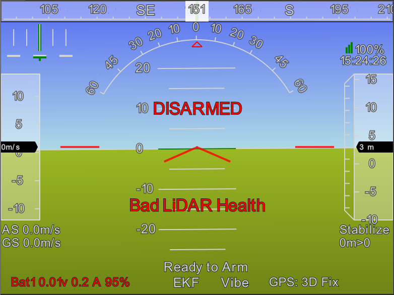
We see the artificial horizon, where the blue part signifies the sky and the green part the ground. Moving our drone while it is connected will result in the HUD moving, and we can use that to verify that our pitch, roll and yaw move in the intended directions. Pitch and roll can be directly seen in the HUD, while we will look at the compass at the top to check our yaw direction.
After we have set the correct orientation for our flight controller, we can go to the Accel Calibration tab.
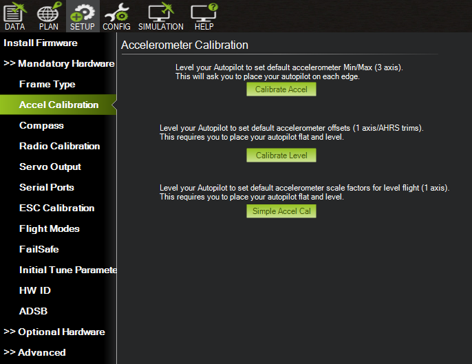
To calibrate the accelerometer, we press the Calibrate Accel button and follow the instructions that will be shown right above the button. This will set the Min and Max values of our accelerometer in all 3 axes by setting our drone on each edge. After calibrating, it is advised to reboot the drone. After we calibrated the Min/Max values, we use the button right underneath and calibrate the level, which will set the default accelerometer offsets. Here and in the first step of Calibrating the acceleration, the drone should be fully level. If it is not, it might lead to the drone drifting, as the level position will be off.
Compass Calibration
Next we will go to the Compass tab to calibrate the magnetometer
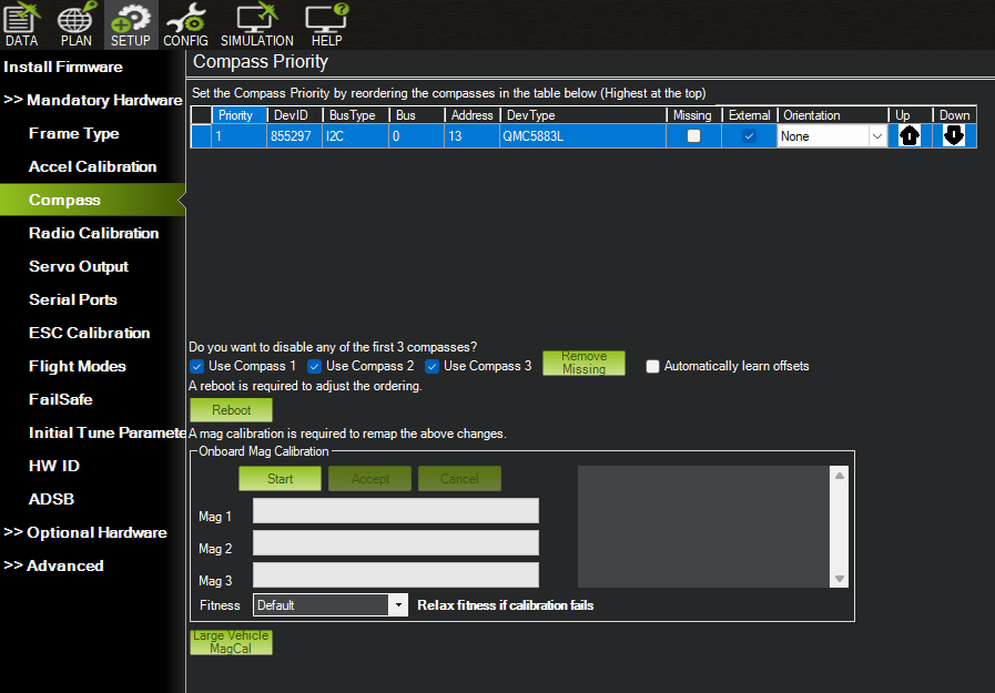
Pressing start will start the calibration, where we will have to rotate the drone around all axes. This will adjust the compass, so that it can read the earth magnetic field more accurately. The process might have to be repeated numerous times, and if it still does not work, it is recommended to go outside, as indoors there might be metal or electric devices that can corrupt the reading of the magnetic field. After a succesful calibration, the values can be saved and the drone will have to be rebooted to finalize it.
Radio Calibration
Radio Calibration is the following mandatory setting.
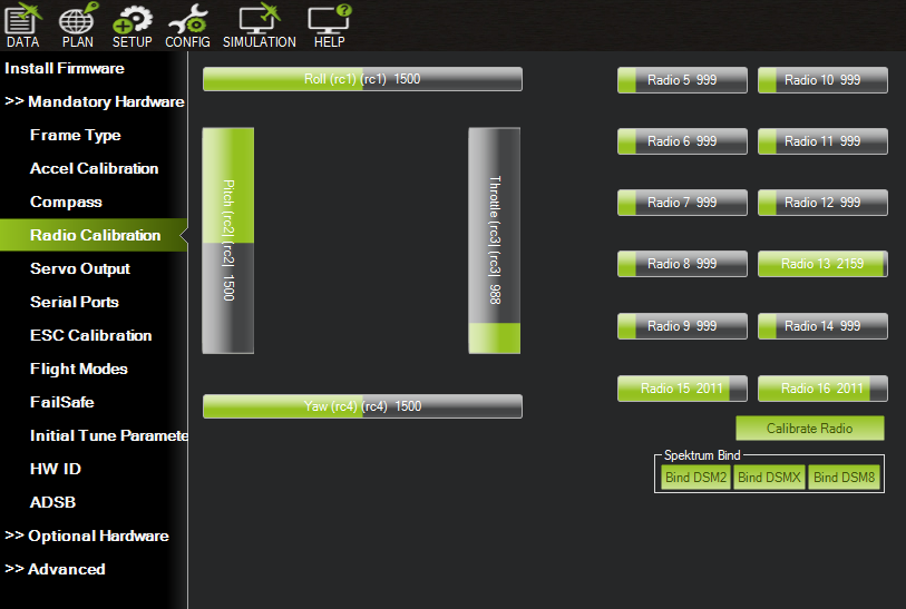
The calibration starts by pressing the button Calibrate Radio, while the receiver has to be connected to the drone. Most important are the roll, pitch and yaw channels, that are controlled using the sticks of the receiver. Normally the centres of the sticks should be exactly at 1500. That is here the case, but it might not always be the case. If the numbers are off, set RC1_TRIM (roll) and RC2_TRIM (pitch) to the PWM value the calibration shows at the stick's centre position. (HS1_TRIM/HS2_TRIM, which older guides mention, are traditional-helicopter parameters and do not exist on the multicopter firmware.) Another important point is that the lower position of the sticks should be below 1000
Servo output, motor test and ESC calibration
This is one of the most important steps. First we define some important terms we will use int the following:
- Electronic speed controllers (ESC): They are controllers that take a high voltage DC power from a battery and low-voltage signal from the flight controller and converts them into complex electrical pulses that make a brushless motor spin.
- Pulse Width Modulation (PWM): This is a technique used to control the amount of power delivered to electronic devices. Instead of reducing continuous voltage , PWM turns the digital signal on and off very fast. The ratio of on and off time simulates a lower average voltage without wasting much energy. In drones the flight controller sends PWM signals to the ESC to tell it how fast to spin the motors. The pulses are for drones mostly between 1000 and 2000 seconds. PWM is replaced by Dshot on newer drone models, but many of the parameter names still contain the PWM notation.
- Digital shot(Dshot): Dshot is a digital communication protocol between flight controller and Electronic speed controllers. Instead of electrical pulses it sends specific digital packets that contain a 16-bit digiral word for every command. 11 Bits are used for the throttle, 1 Bit is used for telemtry requests and 4 Bits are used for a cyclic redundancy check to see if data was corrupted. It has multiple advantages to PWM, it does not need extra calibrations, it is immune to noise created by the motors, and in case of Bi directional Dshot, it can send telemetry data back to the flight controller, allowing the flight controller to use dynamic Notch filters to remove motor vibrations. Generally Dshot is followed by a number that denotes the bitrate in kilobits per second. For example Dshot600 can send 600000 bits per second.
The first thing we will be doing is make sure that our motors are setup correctly. To do that we need to go to the tabs Optional Hardware and the subsection Motor test:
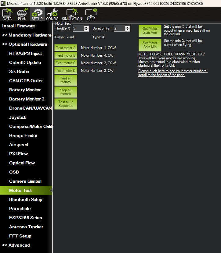
The motor numbering is given for our quadcopter as:
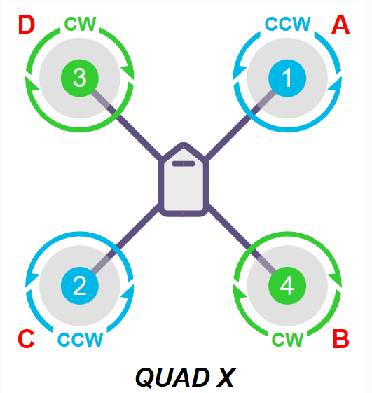
If we have a different Frame type, we will have to look up the correct order under https://ardupilot.org/copter/docs/connect-escs-and-motors.html#motor-order-diagrams
Most ESCs will not directly have the correct motor position using default options. This means we have to look how our motors spin and if they spin in the correct direction. Each motor from A to D should work in clockwise rotation, meaning when we press `Test motor A, the upper right motor should spin counter clockwise, as depicted int he motor numbering image. By pressing Test motor B the lower right motor should spin, and so on. If another motor spins, we have to change the servo output under the mandatory hardware tab:
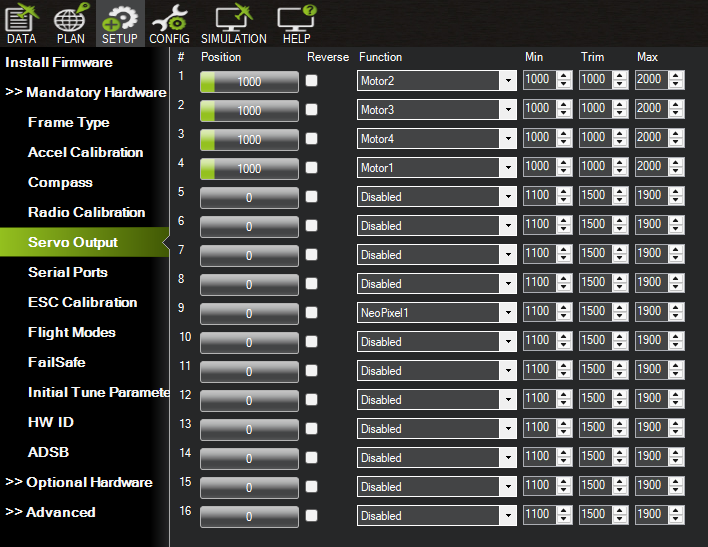
Here we see each motor, the left number shows the position as given in the motor numbering, the Motors in the function column are the actual motors, which we will have to change so they match the correct order we see using the motor test. If the motor spins in the correct place, but spins in the incorrect direction, we can set the checkmark in the reverse column.
In this image we see the correct motor setup for our drone, but do keep in mind, that this is not a general motor distribution and is very likely to be different for a different drone.
Double check that the correct motor spins and that they spin in the right direction according to the diagram for the motor numbers, as the drone will crash if that is not the case.
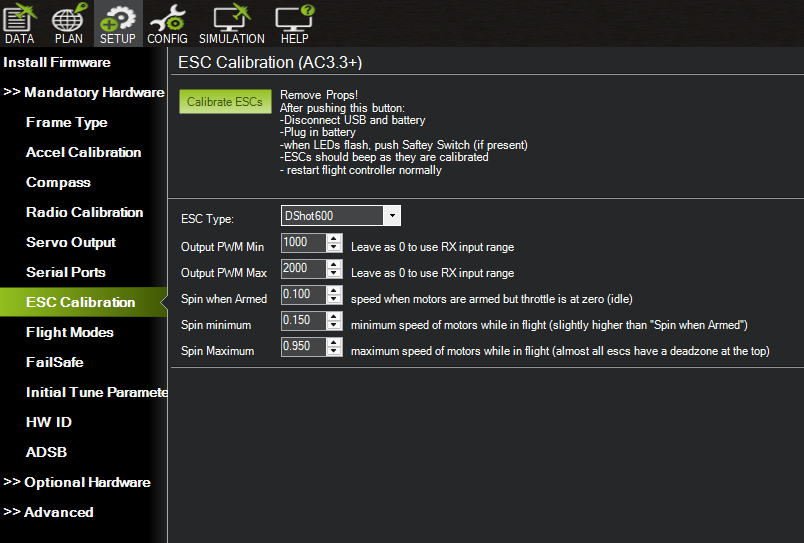
Now there are some more parameters we will have to change for our initial motor setup that define the PWM output range that is sent to the ESC and ensures that the entire range of throttle values used in flight is in linear range of the propulsion system.
- MOT_PWM_TYPE: This parameter is used to select the output PWM type. For DShot300, which we are using, the value should be 5. We ran into problems using DShot of higher rates, like DShot600, as there seems to be too much data for our flight controller to handle. If there are problems regarding ESC tracking, try a lower DShot protocol.
- MOT_PWM_MAX: Sets the maximum PWM output in microseconds, and depends on the used ESC.
- MOT_PWM_MIN: Sets the minimum PWM output in microseconds, and depends on the used ESC.
- MOT_SPIN_ARM: This defines the point at which motors start to spin with values between 0 and 1. Recommended are values betwee 0.05 to 0.1. Important, when armed we want the propellers to spin stably, but the drone should not be about to leave the ground!
- MOT_SPIN_MAX: Sets the maximum spin of the propellers, normally set to 1.
- MOT_SPIN_MIN: This sets the point at which the thrust starts. It should be above the MOT_SPIN_ARM parameter and it is generally recommended to use values betwee 0.1 to 0.15.
- MOT_THST_HOVER: This parameter sets the thrust where the drone is expected to hover. Generally it is expected to be 0.25 or below, but it is highly dependent on the drone.
All the parameters but MOT_THST_HOVER can also be set using the Mandatory Hardware subsection called ESC calibration.
Serial ports
The serial ports in this section are set according to the wiring. In the image at the very top we see the wiring for our drone and set the corresponding ports in this setting:
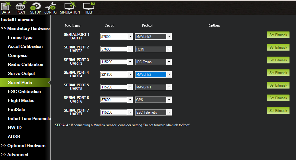
We will go through each serial port that we will have to set based on the wiring of our drone:
- UART 1: Telemetry (DJI VTX), responsible for sending the telemetry data and uses the Mavlink protocol. The baud rate by MAVLink is entirely dependent on the physical hardware, the default value for the industry is 57600 baud. as it is more stable over long distances.
- UART 2: The second serial port is used by the receiver. We set the protocol to RCIN, standing for radio control input. It is a hardware input and can accept and autodecode a variety of digital and analog receiver protocols. The baud rate will be automaitcally set by the firmware, meaning it does not matter to what it is set here. As our receiver is using ExpressLRS, we will also want to change the
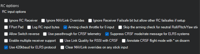
RSSI_TYPE, the radio receiver type, to 3 and set the RC_OPTIONS Bitmask to 'use 420K baud for LRS(Bit 13)', as well as the 'Suppress CRSF mode/rate message for ELRS systems' (Bit9) option. To set the bitmask we go to the Full Parameter List under the config tab and look for RC_OPTIONS.
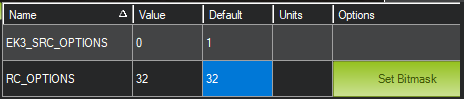
While we could manually set the correct value of the bitmask, we can just click the Set Bitmask button and that will show us all options:
- UART 3: Serial port 3 is connected to our video transmitter that uses the IRC Tramp communication protocol developed by ImmersionRC (IRC) to let the flight controller communicate to our analog video transmitter. The baud rate seems to be at 9600, but the firmware seems to also set this rate automatically, as no baud rate is mentioned at https://ardupilot.org/copter/docs/common-vtx.html
- UART 4: Serial port 4 is set to be used for a onboard computer, namely a Raspberry Pi zero. The flight controller and the computer will use the MAVLink protocol to communicate. The baud rate here can be very high, as we want to share state data back and forth instantly. It is often recommended to set a baud rate of 921600. Higher rates might also be possible.
- UART 5: Serial port 5 is wired to our lidar and optical flow combo. As this sensor is using MAVLink, we set said protcol here. The developer of the sensor recommends a baud rate of 115200
- UART 6: Our serial port 6 is used for the GPS, which is why we set the protocol column to GPS, the handbook sets the baudrate to 115200 bps.
- UART 7: The last serial port is connected to the ESC. There is a physical telemetry wire that runs from the ESC and solders into a RX pin of a UART port and it uses Standard serial communication. In ardupilot, the protocol has to be set to ESC Telemetry and the baud rate is 115200 bps.
Flight Modes
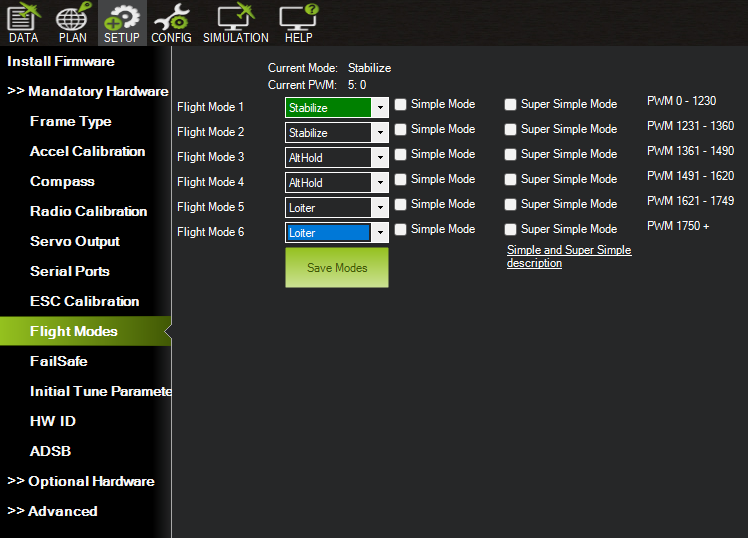
Under the flight modes tab we can set different flight modes that can be changed through a set channel, that is defined through the FLTMODE_CH parameter. Here we see quite a few possible options, but depending on the channel used only some of the modes can realistcally be chosen. For example, most switches on our receiver have only three positions, one beneath 1000 PWM, one at 1500 PWM and one above 2000 PWM, which is also the reason we only have three different flight modes set.
Failsafe
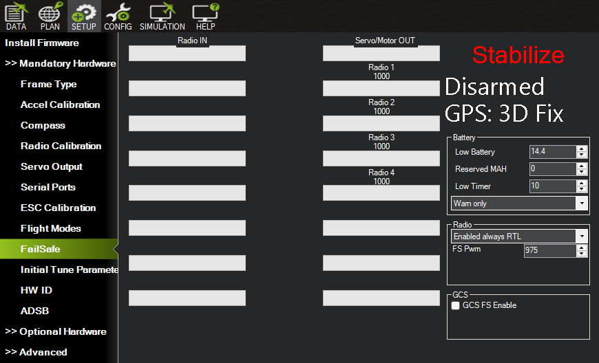
The failsafe tab allows us to set the behaviour of our drone in case the battery is low, or the connection to the receiver is lost. In most cases RTL, return to home and land, is recommended. The problem is, that RTL needs GPS. As we are mainly using the drone to achieve indoor autonomous flight, we generally will not have a GPS signal. This can result in unwanted behavior for RTL, and it is recommended to either just set Land as failsafe, or just give out a warning.
Compass interference
It is possible that the motors influence the compass, this can be checked using Compass/Motor calibration under optional Hardware:
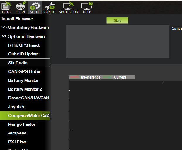
To do the calibration, we flip propellers over, so that the drone is pulling down into the ground. Then we run up to 50% to 75% throttle for 5 to 10 seconds to see how this affects the compass reading. Interference less then 30% is good, less than 60% might be okay, but it could be beneficial to relocate the compass further away from motor wires and battery cables. By readings above 60% the compass should certainly be relocated.
As our compass is located in the GPS and the GPS is located atop a rod, we will not have to to this test, as it is unlikely that the motor influences the compass, but if the compass is located closer to the motor, this test is advised, especially if there are problems with the compass.
Logging
Logging is very important in case something does not work as intended. To set up logging for our drone, we first set sample count to either 1024 or 2048 and set the first inertial measurement unit (IMU1) to log batch data for. A IMU is an electronic sensor pack that measures our drones exact force, angular rate and orientation. They generally have an accelerometer to measure linear motion and a Gyroscope to measure rotational motion and sometimes even a magnetometer that measures the earths magnetic field and allows to know the exact geographic rotation(north, south, east, west) the drone is facing.
IMU1 is generally the primary IMU the drone is using, and because of that it is generally enough to just log IMU1.
The log bitmask should be set as seen in the following image. This setting captures everything that is needed for further tuning the drone.
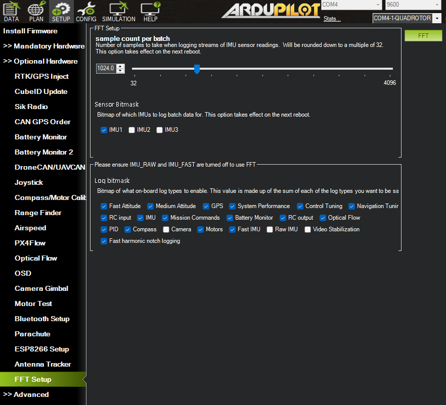
We will also set the options for the BatchSampler INS_LOG_BAT_OPT to log the sensor rate and the sample pre- and post-filter.
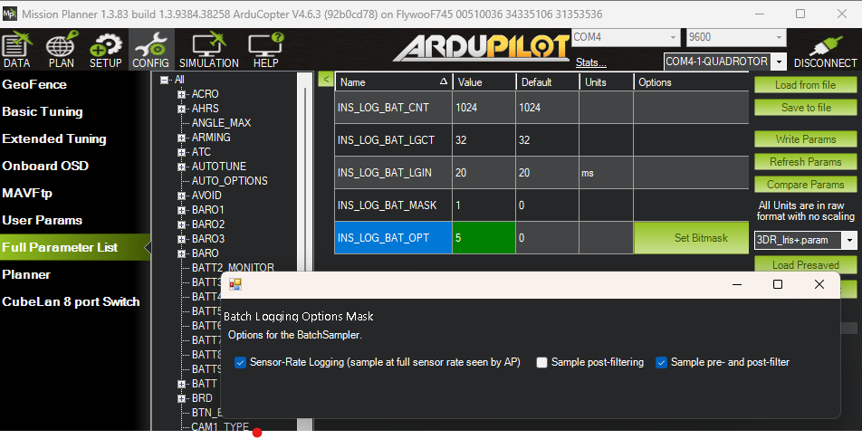
The BatchSampler captures the raw physical noise of the drone. The flight controller is not able to capture every single data point on an SD card, as the card is not fast enough. The BatchSampler triggers a batch sample where ardupilot allocates a small block of RAM memory and pushes every raw IMU reading into the RAM buffer. Once the RAM is full, ardupilot stops collecting data and streams the cached chunk of data onto our storage device as a single ISBH package. This process is repeated multiple times, and the data is needed to tune the harmonic notch filters.
The Flywoo GOKU GN745 chip we are using does not have an SD card slot, but a 16MB SPI flash storage ship, that is used for logging.
For the logger to log onto the memory chip, the LOG_BACKEND_TYPEparameter has to bes set to 4. It also might not be possible to log all of the options we set in our image, and depending on what we want to tune, we might have to only set the corresponding log options.
It is also advised to disable logging while the drone is disarmed by setting the parameter LOG_DISARMED to 0.
Also instead post and pre filter logging for the BatchSampler, we might have to choose just one.
Given the onboard computer is already installed, it is possible to store the logs on the computer instead of the flash storage. We have to set the LOG_BACKEND_TYPE to 2 for mavlink streaming, or to 6 for both mavlink streaming and using the onboard flash memory.
On our Raspberry Pi it is advised to install MAVProxy, ArduPilots official command-line ground station tool and running it as background service. The flight controllers .bin or .tlog files will be stored directly on the Pis micro SD card.
To download a log from the flight controller, we can once again use the Mission Planner.
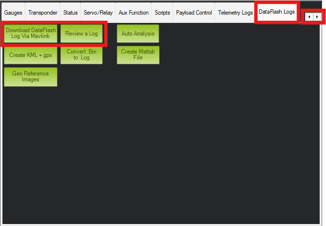
The lower left window shows multiple tabs, which we can scroll through using the two arrows on the upper right. The tab to the very right called DataFlash Logs contains everything regarding logs. To download logs that are currently inside the flash memory on the chip, we can click on "Download DataFlash Log Via Mavlink", that opnes the following window:
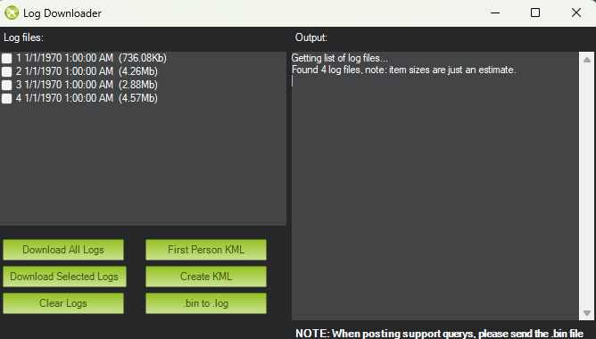
Here we see the logs currently on the flight controller, which we can download. Either we choose certain logs or just download everything. It is advised to regularly delete logs, so the flash memory is not full, which can stop the drone from arming, depending on the arming checks.
To look at our logs, we can use the "Review a Log" option in the "DataFlash Logs" tab.
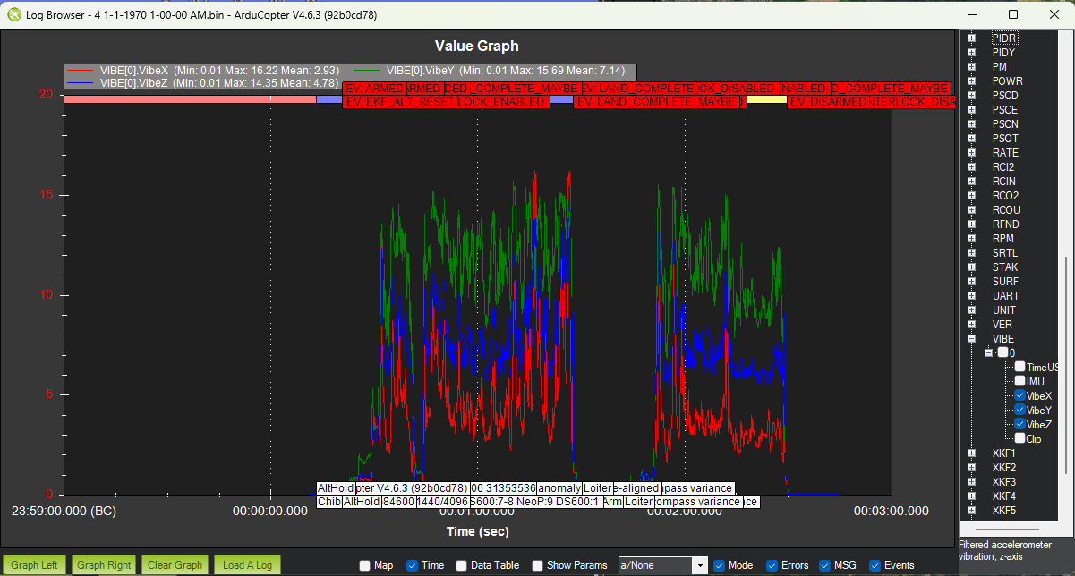
This opens up a new window, where we can see a graph that allows us to graph the data we can choose using the options on the right.
Setup bi-directional DShot
For our logging to work as intended, we still need to make some changes to our DShot settings, namely we want to set Bi-directional DShot, where the ESC will send back the exact revolutions per minute(RPM) of the motor, instead of just getting instructions from our flight controller.
For bi-directional DShot, we first have to set the RPM1_TYPE to 5, signifying using ESC telemetry. When we set the option and write the parameter, more parameters will show up.
From these new parameters we want to set the `RPM1_ESC_MASK' bitmask for all of our motors, which sets each channel that supports ESC rpm telemetry. As our motors occupy channels 1 through 4, we set the value to 15. If they are set to different channels, or you have a drone with more motors, the parameter has to be set appropriately.
Next we set the SERVO_BLH_BDMASK to the same value as `RPM1_ESC_MASK', in our case 15. This sets all channels that support bi-directional DShot telemetry.
To allow the calculation of true RPM form the ESC's eRPM we need to kno the number of magnets in our motors. Generally there are 12 magnets in motors for 3 inch propellers, and 14 is typical for motors for 4 to 10 inch rotors. Our motor type has 12 magnets, so we set the parameter SERVO_BLH_POLES to 12.
Lastly we also set the SERVO_DSHOT_ESC parameters, that specifies the ESC type for all outputs. In our case we have a AM32 flight controller, so we set the value 1, that is used for Kiss/AM32/BL32 controller, whereas 2 is used for Bluejay.
Some newer ESC types also support Extended DShot Telemetry(EDT), where more data than just the RPM data is returned through bi-directional DShot, which we can enable through the value 3 for Kiss/AM32/BL32 controllers and through using 4 for Bluejay controllers.
Setup initial Harmonic notches
First off we want to thank Nur Uddin Syeed for setting up the notch filter on our drone. The following information is based upon AI-Drones, the book he co-authored, as well as the work of Chris Rosser, that has a full Tuning Guide on youtube, and the official documentation of how to measure vibration and how to configure the notch filter.
Vibrations
The autopilot of our drone uses accelerometers, rangefinders and GPS or optical flow sensors to estimate the drones position. Excessive vibrations can affect the accelerometers and the position estimate can be thrown off, resulting in bad performance, especially in flight modes that need accurate poitioning, as Position Hold, Loiter or Guided mode.
We can directly see the vibrations inside the Ground station. Inside the Data tab, in the heads up display on the upper right, we can click on vibe,
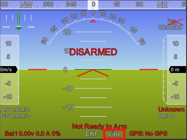
which opens a little popup, that allows us to measure vibration in flight.
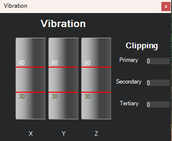
In general, we want Vibration levels to be beneath \(30m/s^2\), as levels above might already lead to a degraded performance of our drone. Levels above \(60m/s^2\) almost always lead to problems in regards to position estimation, making it impossible to use modes like Loiter or Guided, which we need for our autonomous flight.
As we might not necessarily have a connection to our Ground Control Station, we can also use the Log we already set up. We navigate to "Review a Log", just as described in the logging section, and open a Graph. On the right side we can choose what to graph, in our case we want to graph the vibrations, which are given as the parameters VibeX, VibeY and VibeZ, that show vibration in the corrseponding directions.
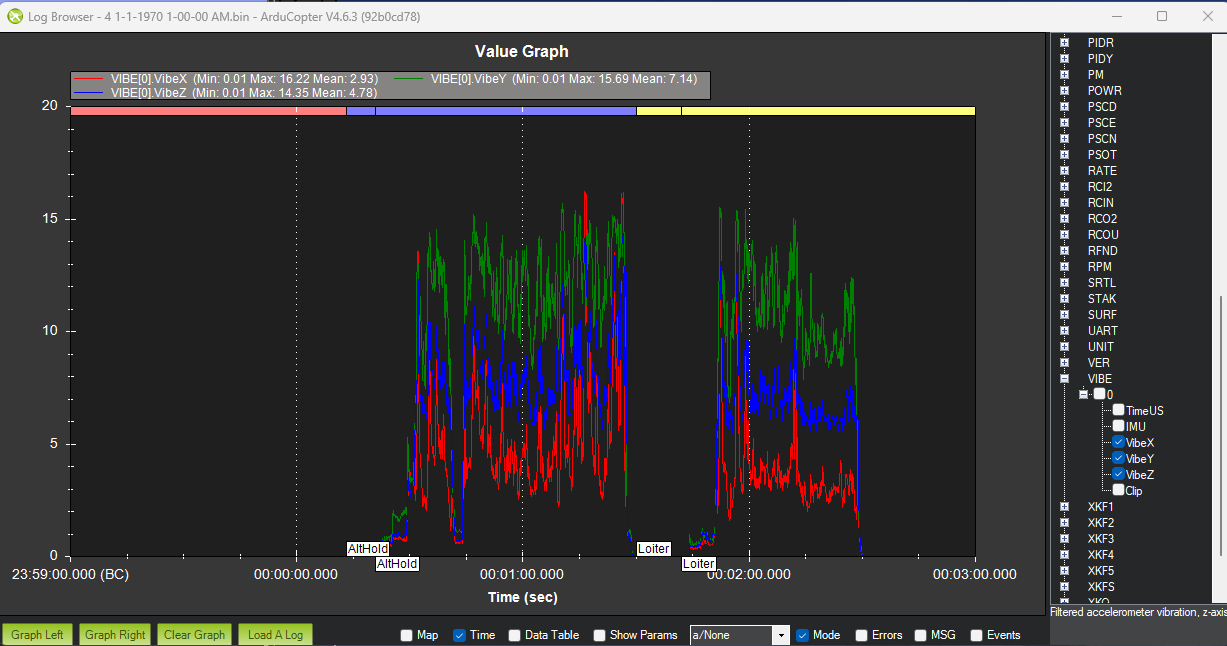
We can see, that in this graph the vibration level is well below \(60m/s^2\), meaning there is no need to further dampen vibrations. When we look at the example provided by Ardupilot for high vibrations, that will result in bad drone performance:
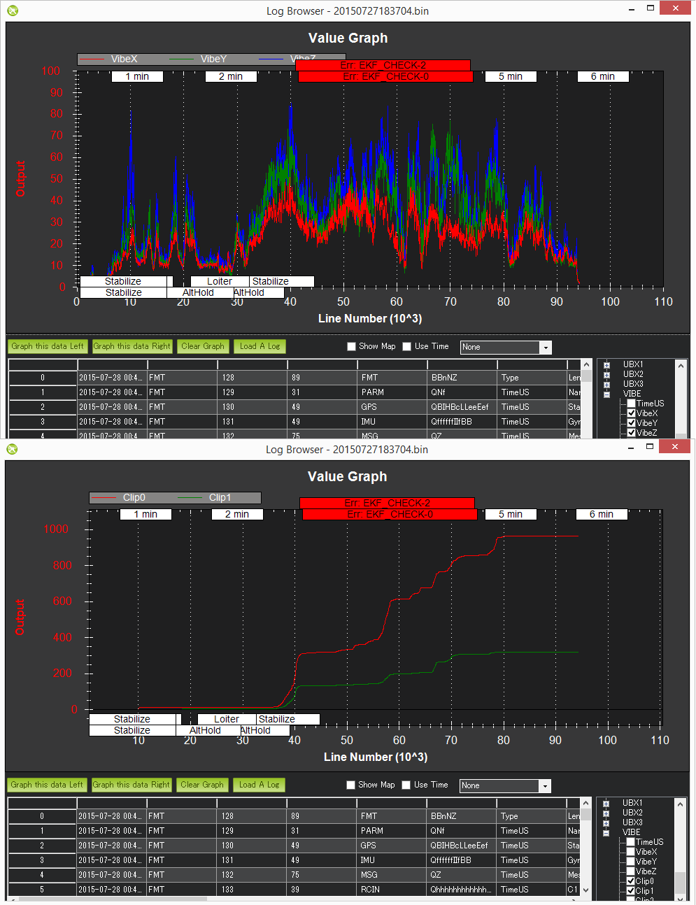
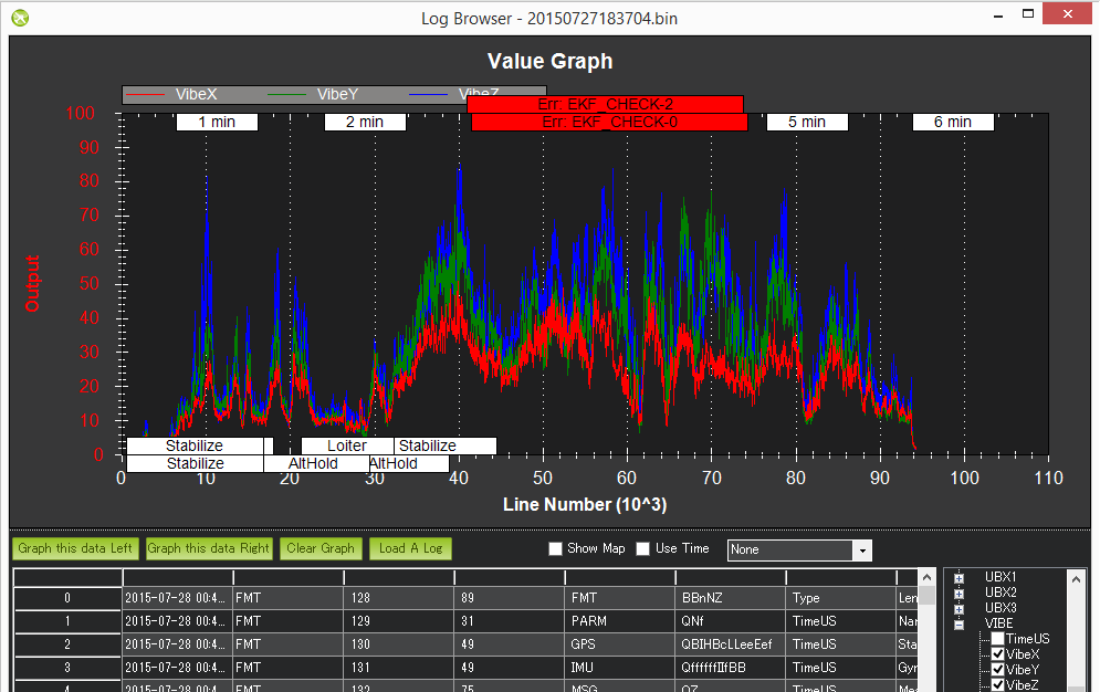
The values of the graph are regularly far above \(60m/s^2\). If you see a graph like this, you may need to look at more involved solutions, that can be seen in Vibration Damping
For bad Vibration issues we will also see multiple accounts of clipping, where physical vibrations push the flight controllers accelerometers past their measurement limits, as seen here:
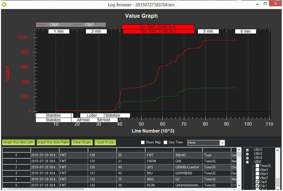
Generally we want zero occurence of clipping events. If you see any clipping, try to reduce the vibrations.
To reduce the most extreme mechanical vibrations, we can use some of the options ardupilot has documented under Vibration Damping, but we need software filtering to remove further noise.
There are three filter possibilities provided by Ardupilot.
- Lowpass filters on accelerometer and gyro signals, controlled using the parameters INS_ACCEL_FILTER and INS_GYRO_FILTER respectively.
- Attitude and Altitude rate PID loop filtering for different inputs:
- Attitude of reference inputs, controlled by
- ATC_RAT_RLL_NTF
- ATC_RAT_PIT_NTF
- ATC_RAT_YAW_NTF
- Attitude of error inputs, controlled by
- ATC_RAT_RLL_NEF
- ATC_RAT_PIT_NEF
- ATC_RAT_YAW_NEF
- Altitude acceleration controlled by
- PSC_ACCZ_NTF (before 4.7) / PSC_D_ACC_NTF (after 4.7)
- PSC_ACCZ_NEF (before 4.7) / PSC_D_ACC_NEF (after 4.7)
- Harmonic Notch Filters on gyro signals, that are controlled by
- INS_HNTCH_ENABLE
- INS_HNTC2_ENABLE (for a second set of Harmonic notches)
Notch filter
Here we will concentrate on the last point, the Harmonic Notch Filters. For our multicopter, most vibrations are generally caused by the motor's rotational frequency, which provides notches at a primary frequency, as well as its harmonics.
Ardupilot allows for two dynamic notch filters, where the filter frequency is linked to the rotational frequency of the motors.
The first step is to enable harmonic notch filters, which we can do through the parameter
INS_HNTCH_ENABLE = 1 for the first notch and INS_HNTC2_ENABLE=1 for the second notch.
Having two notches takes quite a lot of computing power and might not be possible depending on the flight controller. We will be using only one notch.
There are 5 different modes using notches:
1. INS_HNTCH_MODE = 0:\
This mode is using a static center frequency, this means there is no dynamic notch frequency control is fixed.
2. INS_HNTCH_MODE = 1:\
This mode is based on the throttle position. The frequency at hover throttle can be determined using the logs and the variation of the throttle position is used to track the increase in noise frequency. An ardupilot guide can be found here: Throttle Based Dynamic Notch Setup
3. INS_HNTCH_MODE = 2:\
This mode is based in an external RPM sensor, that is used to determine the motor frequency, that is the primary vibration source, to determine the notch.
4. INS_HNTCH_MODE = 3:\
This mode uses the ESC telemetry to get the RPM information of the motor for the notch. This is the best mode for flight controllers that support bi-dircetional DShot, as it automatically adapts and is easy to set up, while not needing the computational requirements of the FFT(following mode)
5. INS_HNTCH_MODE = 4:\
This mode uses the Fast Fourier Transformation (FFT) to determine the primary noise frequency for adjusting the notch. This is according to the Ardupilot documentation the best mode, but flight controllers should have 2MB of memory, which is not the case for the flight controller used here. A in-depth guide for setting this up can be found here: In-Flight FFT-Based Harmonic Notch Setup
We will concentrate on INS_HNTCH_MODE = 3.
First we determine the notch filter center frequency. They are needed for both the static center frequency (Mode 0) and the throttle based method (Mode 1), but because we want to identify which harmonics of the center frequency we want to filter out, it is also helpful to know, what the center frequency is for the method using ESC telemetry. We can do this using the Filter Review Tool provided by Ardupilot.
After providing a log file to the tool, we can see different graphs inside it. Our main focus is on the IMU spectrum:
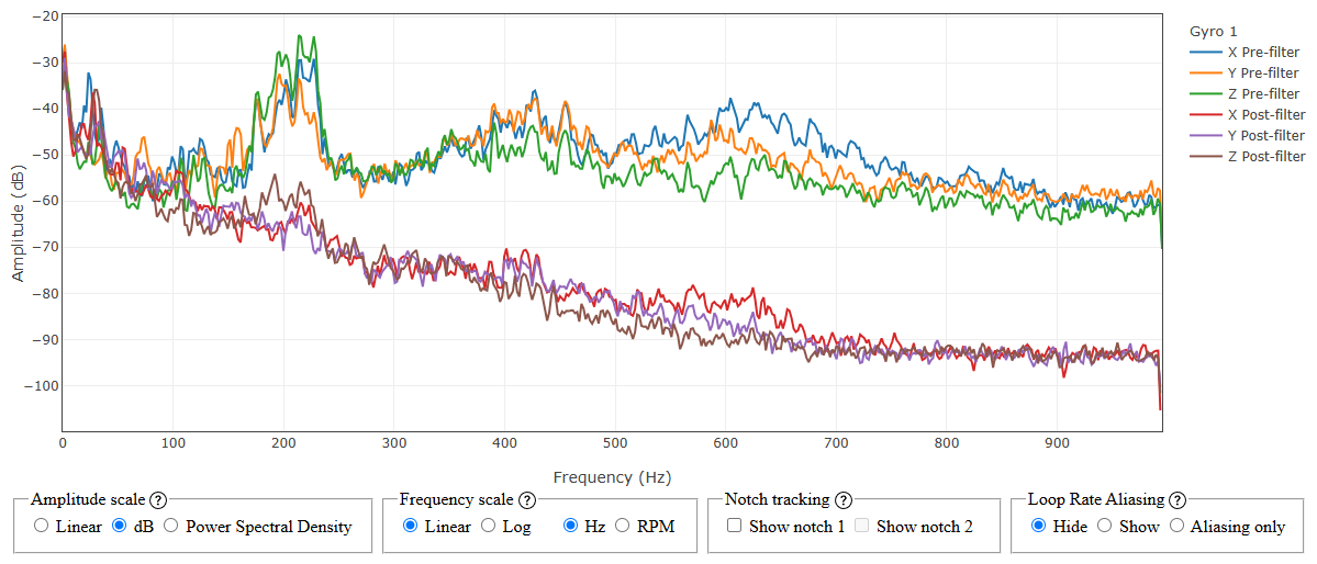
We can see a quite significant bump, a noise peak, in amplitude around 213 Hz, this will be the center frequency. If we use either the static center frequency or the throttle position mode, we will need to set the two parameters INS_HNTCH_FREQ to the center frequency and INS_HNTCH_BW, that sets the bandwidth of the filter, to half the center frequency. In our case it would look like the following:
As the mode using ESC telemetry to calculate the frequency dynamically based on the measured RPM, we do not need to set the center frequency, but we still need to specify the harmonics that are used by the notch, we can do this by looking at the IMU spectorgram:
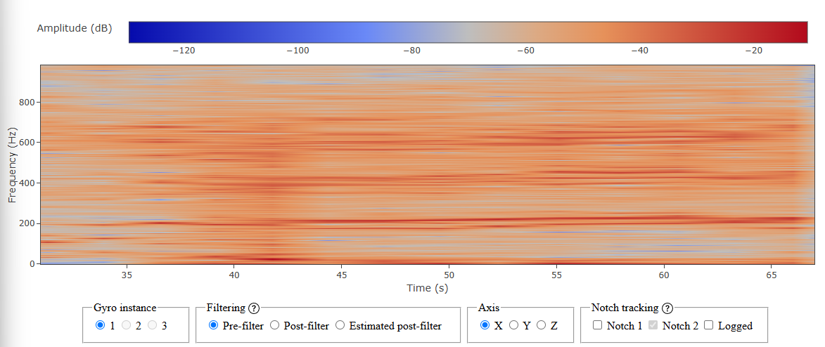
We are interested in the red lines inside our graph, as these correlate to high amplitudes of the frequencies. The lowest red lines we see are caused by the rigid body movement of the drone. We are mainly interested in the red line at our center frequency, here around 213 Hz. This is the base frequency, and we want to look at the harmonics, multiples of the base frequency, that add significant noise as well. In our case we also see thicker red lines around 420 Hz and a little above 600 Hz. These are the second and third harmonic of our base frequency.
To set the harmonics, we change the INS_HNTCH_HMNCS parameter. We can just click at the Bitmask button
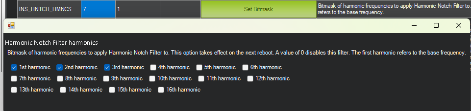
and set the needed harmonics, in our case we use the value 7. Ardupilot allows for up to 16 Harmonics, but because of computational limitations, the number of harmonics should be kept as low as possible.
Another parameter we need is INS_HNTCH_OPTS that controlls the configuration harmonic notches as multiple notches, that can give a wider spread of significant attenuation. The options are:
- Double overlapping notches, where two notch filters are stacked closely over the same frequency band, allowing for deeper attenuation across a wider bandwidth
- Multisource, where in ESC mode each motor will have a notch assigned at its respective RPM. In FFT mode the three largest noise sources are assigned a notch, and for throuttle mode each motor will have a notch assigned at its throttle input.
- Update filters at loop rate, meaning the notch center frequency is updated at the scheduler loop rate.
- This option enables the notches on every IMU instead of only using the primary IMU
- Triple overlapping notches, for similar reasons as double overlapping notches
- This option allows for using the given center frequency, in case the RPM source fails.
For our use case we use option 1 for multisource, so every Motor has a notch assigned, and option 2 for faster updating of the center frequency.
The Filter Review Tool allows us to directly see the notches for our given specifications as well. Given our drone and setup, we get the following:
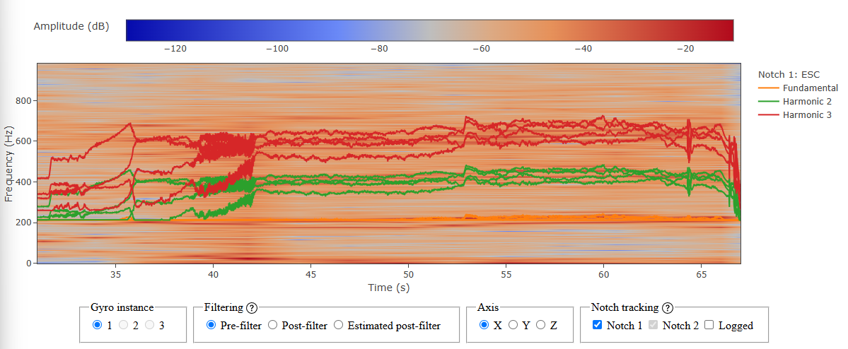
For each harmonic we see four lines. This is because of the multisource, as each Motor has its own notch based on its individual RPM. We also see, that they pretty much cover the red lines. After filtering, the specogram looks like this:
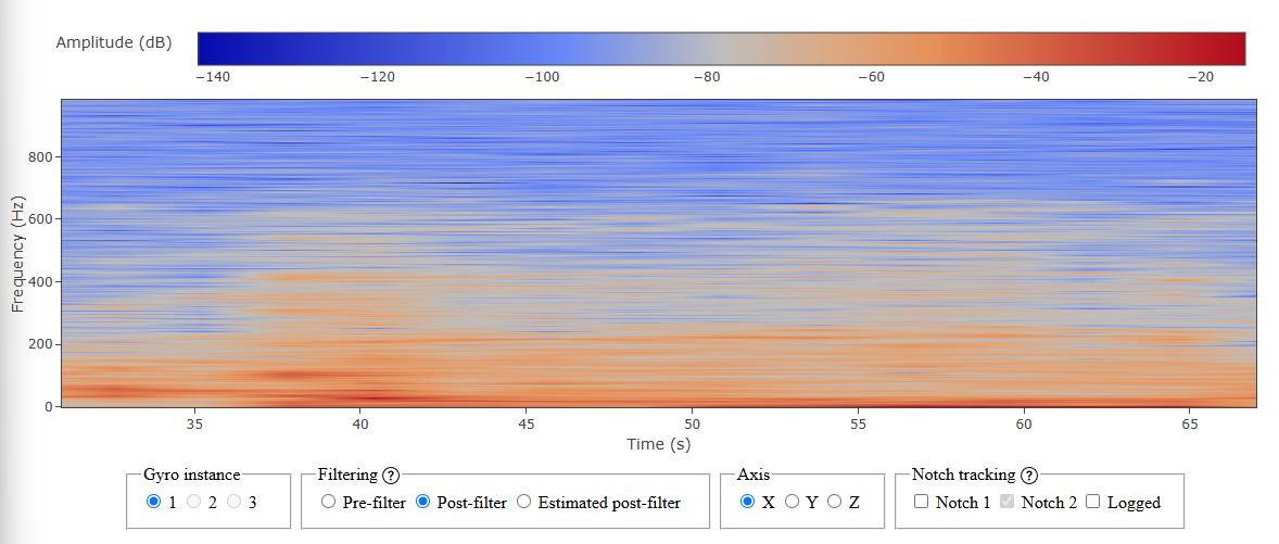
which is a large improvement regarding unwanted noise.
Set up indoor flying
Ardupilot is very reliant on the GPS, which is problematic if we are trying to fly our drone in an indoor setting, where we generally will not have a GPS connection.
Some important settings we have to set are the failsafe actions. While for outdoor activity, generally the RTL option, that returns to the starting point, is recommended, in indoor environment this can lead to problems, as the drone will try to reach RTL altitude, which generally is higher than the ceiling.
We already set the failsafes in the Failsafes section. Indoors the goal is "never RTL", not "no failsafes": RTL climbs to RTL_ALT first (into the ceiling), but a drone with all failsafes off keeps flying with a dying battery or a dead RC link, which is strictly worse.
We can also look at the Full parameter list. each parameter that is associated with the Failsafe settings starts with FS
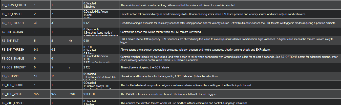
The indoor-safe values are:
| Parameter | Value | Meaning |
|---|---|---|
FS_THR_ENABLE |
3 |
Radio (throttle) failsafe → Land where it is, instead of the default RTL |
FS_EKF_ACTION |
1 |
EKF failsafe → Land. Do not disable this: a diverged position estimate flying on is the textbook indoor flyaway |
FS_GCS_ENABLE |
5 (Land) or 0 |
Reaction when the ground station / companion falls silent. 0 is defensible in a hall, but then a dead companion has no automatic rescue |
FS_DR_ENABLE |
0 |
Dead-reckoning failsafe needs GPS, meaningless indoors |
BATT_FS_LOW_ACT |
1 |
Low battery → Land, not RTL |
To make sure the drone starts safely, we can use the following steps:
- Ground-drift GO/NO-GO before every arming (
preflight.py): the divergence is quadratic, so seconds of EKF-altitude drift on the disarmed aircraft already print a DO-NOT-FLY verdict. - Bench hand-lift test proving the EKF altitude actually follows a real lift before any flight.
ARMING_CHECK = 786390: everything except the GPS lock that can never pass indoors.- Geofence off: no barometric fence inside the takeoff downwash noise band.
- Rangefinder-gated pilot takeover (
--takeover): the handover trusts the raw rangefinder, not the EKF altitude, and refuses when the two disagree. - Continuous in-flight EKF-vs-rangefinder cross-check (
EKF_ALT_DIVERGED→ LAND). RNGFND1_GNDCLEAR = 5: the parameter's own minimum settable value in Mission Planner. The value2, matching the true ~2 cm mounting height, was tried and refused (see the rangefinder block above).
To allow for position hold and autonomous flight we will also need a optical flow sensor and rangefinder. The rangefinder can tell the drone its correct altitude and the optical flow sensor can track the movement of the ground using a small camera.
First we setup our optical flow sensor. On the flight controller side, all parameters we need are given in https://ardupilot.org/copter/docs/common-mtf-01.html. Our drone has the sensor set at our serial port 5, using another serial port parameters SERIAL5 will have to be corrected to the appropriate serial port. As our sensor uses the MAVLink protocol, we will have to set the corresponding values for the serial port and the optical flow type, as well as for the rangefinder we are using, in this case the first.
SERIAL5_BAUD= 115: This sets the baud rate for our serial port 5.SERIAL5_PROTOCOL= 1 This sets the protocol that is used by the serial port 5, in this case MAVLink1 for our Micoair optical flow sensor.FLOW_TYPE= 5: This sets the optical flow sensor type to MAVLink.RNGFND1_TYPE= 10: Sets the rangefinder type to MAVLink.
Not all parameters are shown when some parameters are not set. The rangefinder parameters are only shown after we set a value for RNGFND1_TYPE, which means we need to reboot our drone for the following parameters to show up.
RNGFND1_MAX_CM= 800: This parameter sets the range finder’s maximum range, in centimetres on ArduCopter 4.6.RNGFND1_MIN_CM= 1: sets the minimum range in centimetres. Not the 20 cm default: the MTF-01P sits only a few cm above the floor; with a higher minimum the driver reports "out of range low" on the ground, the EKF gets no terrain height, optical flow cannot be scaled and arming fails with "Need Position Estimate".RNGFND1_ORIENT= 25: sets the orientation of the rangefinder, in our case we want it to be downwards.RNGFND1_GNDCLEAR= 5: ground clearance in centimetres. The sensor's real mounted height is only about 2 cm above the floor, and2was the value we originally tried in Mission Planner, but the firmware refused it. On this ArduCopter build,5is the parameter's own minimum settable value, not a re-measurement, so we adopted5instead of the 10 cm default as the closest achievable approximation, even though it now overstates the true mounting height by about 3 cm. EKF3 treatsRNGFND1_GNDCLEARas the rangefinder reading it should expect when the aircraft is landed, so an over-large value biases the height the filter sees on the ground. Getting this value as close as the firmware allows to the true mounting height is one of the mitigations we are testing for the on-ground divergence (see the danger box below).
RNGFND1_MIN/RNGFND1_MAX (in metres) are the 4.7 names
On our pinned 4.6.3 they do not exist, and ArduPilot silently ignores unknown
parameter names. Setting them "works" and changes nothing. Use the _CM names
above and verify by reading the values back.
We will also have to make some changes to our Extended Kalman filter, that uses some sensors to estimate vehicle position, velocity and angular orientation, which we base on the article found at https://ardupilot.org/copter/docs/common-optical-flow-sensor-setup.html. The default parameters use the GPS for estimating the position and velocity, a barometer for the altitude and a compass for yaw orientation. We will specify both the default and new options. It is also possible to use multiple source configurations for our extended kalman filter, that can be switched in flight.
The default parameters that are set for the extended Kalman filter:
EK3_SRC1_POSXY= 3 (GPS)EK3_SRC1_POSZ= 1 (Baro)EK3_SRC1_VELXY= 3 (GPS)EK3_SRC1_VELZ= 3 (GPS)EK3_SRC1_YAW= 1 (Compass)EK3_SRC_OPTIONS= 0 (Disable FuseAllVelocities)
The parameters we are using for indoor flight are:
EK3_SRC1_POSXY= 0 (None)EK3_SRC1_POSZ= 2 (Range Finder)EK3_SRC1_VELXY= 5 (Optical Flow)EK3_SRC1_VELZ= 0 (None)EK3_SRC1_YAW= 1 (Compass)EK3_SRC_OPTIONS= 0 (Disable FuseAllVelocities)
We set the parameter EK3_SRC_OPTIONS to zero, to avoid that the drone fuses all velocities, as fusing velocities of GPS and optical flow will lead to problems, especially if the GPS coverage is spotty at best.
Further we have to set the actual position in XY axis EK3_SRC1_POSXY and the velocity along the z-axis EK3_SRC1_VELZ to none, as we do not have the necessary sensors to accomplish such calculations and keeping the GPS would lead to complications.
If we need to be able to access both settings for the extended Kalman filter, we can set one of the setting sets to SRC2 or SRC3, and set one of the RC options to 90. This allows us to change the sources on the fly.
Hover test
The initial setup is completed, and we can start our first flight of the drone. For the first flight we will start in stabilize mode. After arming the drone we slowly increase the throttle until the drone leaves the ground. There will be many possible problems in the first flight, and we will address some of the most common.
- The drone does not arm: Ardupilot has a lot of different checks it makes before arming, that are saved in the
ARMING_CHECKparameter.
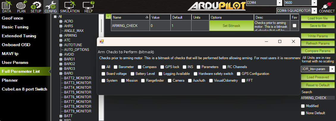
As we are trying to use our drone indoors, it will generally be a problem to get a GPS lock, which might stop the drone from arming. Disable only the GPS check, never all of them:. In our case we set ARMING_CHECK = 786390, which is every check except the GPS lock. This value can change depending on the firmware used.
- The drone tries to flip upon increasing throttle:
There are mutilple reasons that might happen:
- This could mean that there is a problem regarding the motor setup and we should make sure that they are in the correct order and spin in the right diretion using the motor test.
- The orientation is set up incorrectly and the drone believes to be on its head. In this case we will have to change the orientation like we did in the section about acceleration calibration and orientation.
- Propellers are not mounted correctly
-
The drone leaves the ground but oscillates strongly: If the drone oscillates strongly, there is generally a problem in the PID controllers. As a start for later tuning, it is recommended to reduce the following PID parameters of the roll and pitch PID controllers by 50% until we no longer see the oscillations:
- ATC_RAT_PIT_P
- ATC_RAT_PIT_I
- ATC_RAT_PIT_D
- ATC_RAT_RLL_P
- ATC_RAT_RLL_I
- ATC_RAT_RLL_D
If we no longer observe oscillations, we can increase the values by 10%, until we once again see oscillations, and back off to the last used values where no oscillations were observed.
In extreme cases the vibrations can blind the gyroscope, leading to the flight controller thinking the drone is tilting violently and while trying to correct the orientation sets the motors to full throttle, leading the drone to ignore RC inputs and flying away with full speed.
-
The drone leaves the ground, but the inputs do not match the movements of the drone
- The orientation of the drone might be wrong, resulting in the drone moving differently then intended. In this case look at the acceleration calibration and orientation section to
- If the Mission planner HUD shows the correct movements, but the drone still does not move in the right direction, the axis might be reversed. For example, Betaflight has a reversed pitch axis compared to ardupilot. If that is the case, we need to set the RC reversed bit. For the pitch axis we would set
RC2_REVERSEDto 1, which was the case in this particular drone.
-
The drone flies normally but drifts away:
- The center of Gravity might be off. Make sure the center of gravity is dead center of the drone and run the level command on a fully flat surface. Another possibility is to run in auto-trim mode in a windless environment. It is important that there is no wind, as the trim will take that into account and the problem might worsen in another environment.
- The PWM value at the center positions of the sticks is not exactly 1500. When the drone thinks the center position is off, the drone will drift. Make sure the parameters
RC1_TRIMfor roll andRC2_TRIMfor pitch match the PWM registered for the center position.
-
The drone yaws to the right or left on takeoff: This generally happens when the airframe is out of tune and one of the motors is slightly tilted or the weight balance is not centered. In most cases the drone will yaw around 30 to 45 degrees on takeoff and then the PID controller kicks in to stabilize the rotation. It is possible to adjust the PID terms to mitigate the problem to some extent, but as it does not solve the root problem, it is advised to look at each motor and see if any of the arms is slightly tilted and bend it back to vertical in case it is. Alsot the frames balance might be off center, make sure the battery is centered and redo the acceleration calibration if needed.
-
The drone yaws when pitching or rolling: If this is the case, there might be a problem regarding the compass, which needs calibrating.
Sources
- Drone Handbook: https://github.com/christianbaun/aidrones
- A list of all ardupilot parameters can be found at: https://ardupilot.org/copter/docs/parameters.html
- Initail tuning parameters: https://ardupilot.org/copter/docs/setting-up-for-tuning.html
- PID-controllers and tuning:
- https://ardupilot.org/plane/docs/new-roll-and-pitch-tuning.html
- https://ardupilot.org/dev/docs/apmcopter-programming-attitude-control-2.html
- https://www.youtube.com/watch?v=9laDDE3tv-g
- CRSF Receivers: https://ardupilot.org/copter/docs/common-tbs-rc.html#common-tbs-rc
- Common problems: https://ardupilot.org/copter/docs/troubleshooting.html
- GPS and Non-GPS transitions:
- https://ardupilot.org/copter/docs/common-non-gps-to-gps.html#common-non-gps-to-gps
- https://ardupilot.org/copter/docs/common-non-gps-navigation-landing-page.html
- Extended Kalman Filter:
- https://ardupilot.org/copter/docs/common-apm-navigation-extended-kalman-filter-overview.html
- Handbooks
- Frame: https://www.christianbaun.de/Master_Projekt_SS2026/Dokumente/SpeedyBee-Bee35-Manual-EN.pdf
- Flight controller: https://www.christianbaun.de/Master_Projekt_SS2026/Dokumente/F745-V3.pdf
- Video sender: https://www.christianbaun.de/Master_Projekt_SS2026/Dokumente/TX800-manual_EN.pdf
- Motors: https://www.christianbaun.de/Master_Projekt_SS2026/Dokumente/10787-1080.jpg
- GPS: https://www.christianbaun.de/Master_Projekt_SS2026/Dokumente/HGLRC_M100_5883_GPS.pdf
- Receiver: Radiomaster XR4 (ExpressLRS) — see https://www.radiomasterrc.com/ and https://www.expresslrs.org/ (an earlier revision of this list linked the GPS handbook here by mistake)